Mechanical Engineering Student
ZAID
Curious across mechanical engineering — design, analysis, and hands-on builds from the lab to the field.
Zaid Alsalihi · Southern California · Open to internships & full-time roles
In the shop
Hands-on work — prototyping on the bench and machining in the lab.

Portrait 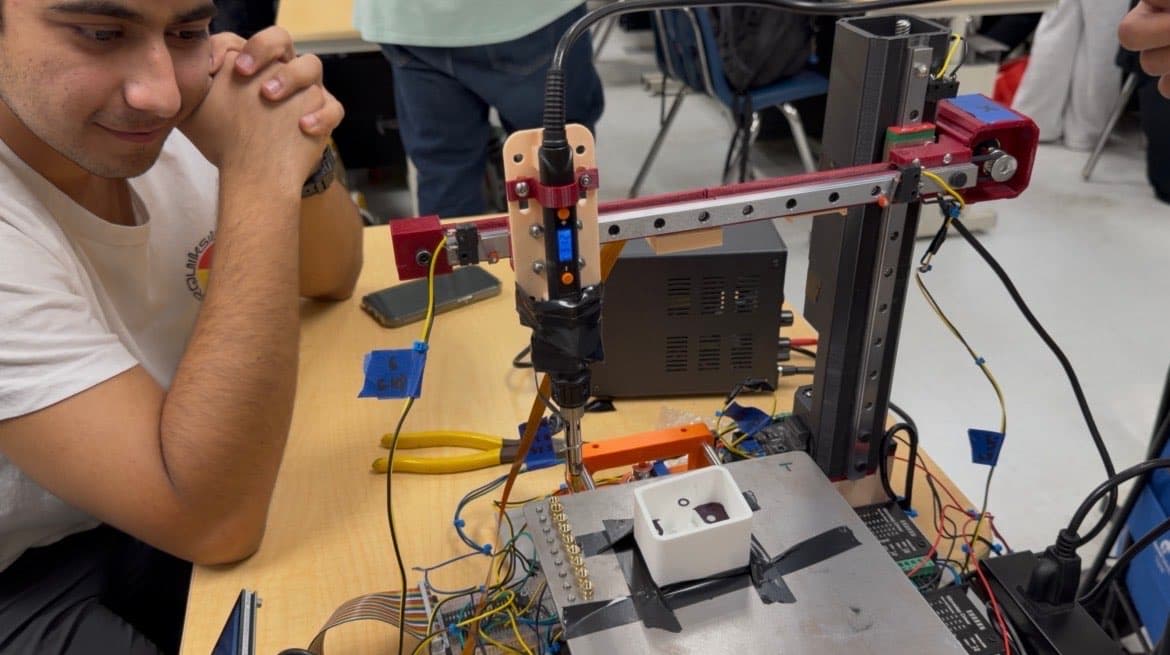
Build & test 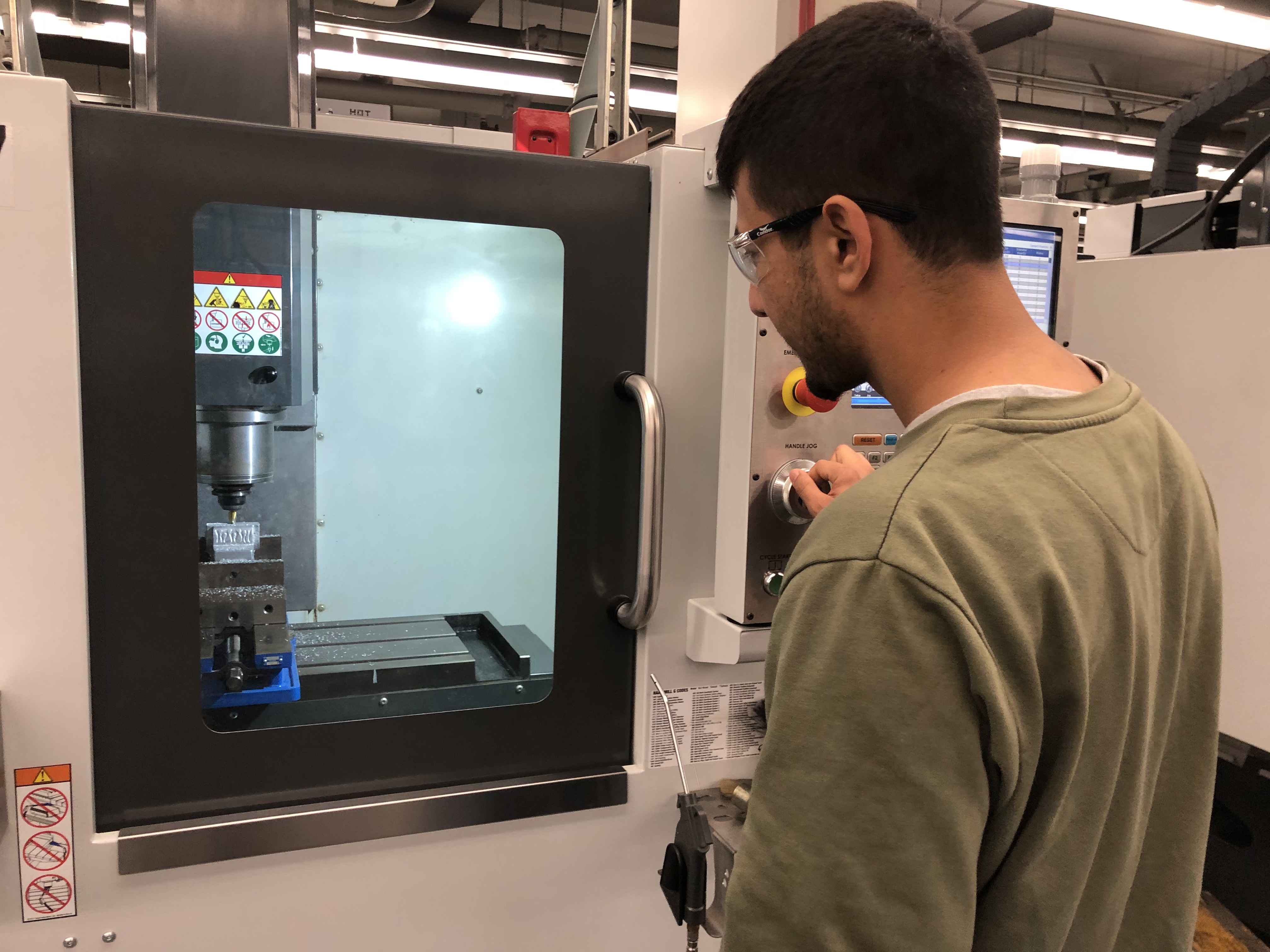
Shop floor
About
About me
I’m a first-generation college student in my family. We immigrated to the United States in 2013, and I grew up in a single-parent household — that path set me up with discipline and focus that I bring into every class, lab, and build.
At Cal Poly Pomona I’m studying mechanical engineering and keeping my interests wide open — design, analysis, manufacturing, aerospace, and real-world systems. I started at Cypress College (A.S. in Mathematics and Physics), co-founded the engineering society there, and have spent summers in industry on thermal/fluid systems and mechanical project coordination. Outside class I led aerodynamics for the Flying Broncos and completed NASA community-college engineering programs.
- First-generation college student · immigrated to the U.S. in 2013
- Cal Poly Pomona B.S. Mechanical Engineering · Dec 2026
- Cypress College A.S. Mathematics & A.S. Physics · May 2024
- Curtis and Jill Scheetz Family Outstanding Campus Leader Scholarship
- Maximizing Engineering Potential & NSF Bridge Program
- School
- California State Polytechnic University, Pomona
B.S. in Mechanical Engineering · Dec 2026 - Transfer path
- Cypress College — A.S. Mathematics & A.S. Physics (May 2024)
Selected work
Projects
Two design-and-build highlights for now — the heat-insert machine and the Can Arm transfer robot. Expand a row for CAD, drawings, video, and the full build story.
Threaded inserts give 3D-printed parts durable, reusable threads, but installing them by hand is slow and inconsistent. I established and built an automated heat-insert machine: a rigid aluminum base with integrated Y-axis motion, a belt-driven X-axis and lead-screw Z-axis gantry, a stainless work bed with insert staging on dowel pins, and a heated toolhead that picks and seats inserts. The system uses stepper-driven motion, homing sensors, and a Pi camera for hole detection — similar in architecture to a compact CNC/3D-printer gantry, purpose-built for repair and insert placement.
CAD & mechanism views
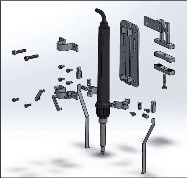
Exploded toolhead & clamp assembly — SolidWorks 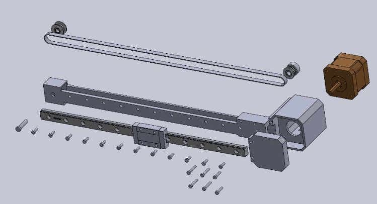
X-axis exploded — belt, rail, pulleys, stepper 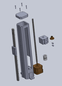
Z-axis exploded — lead screw, rail, motor 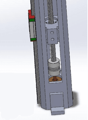
Z-axis detail — coupler, lead screw, carriage 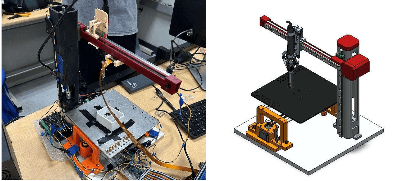
CAD assembly vs. physical build 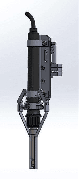
Toolhead assembly render 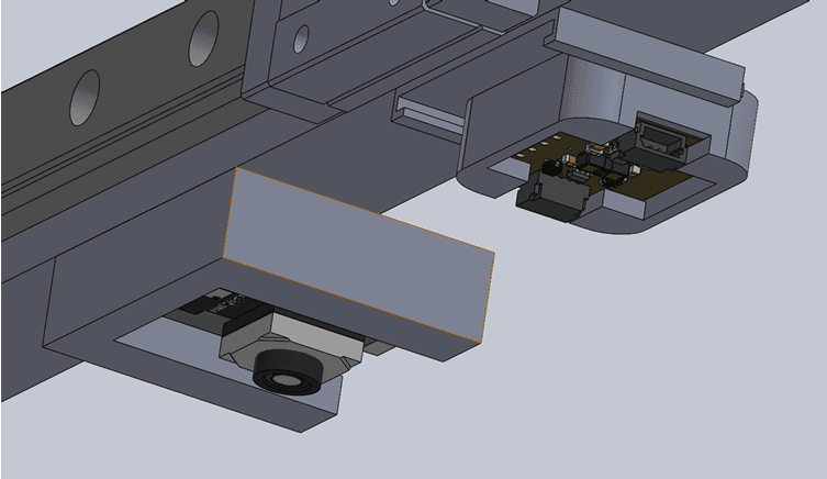
Sensor / camera housing mounts
Manufacturing drawings
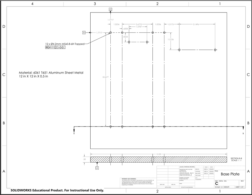
Base plate drawing — 6061-T651, M5 taps, GD&T (Zaid A.) 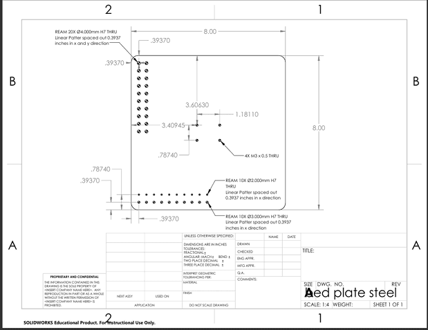
Bed plate steel drawing — reamed insert staging holes
Build photos
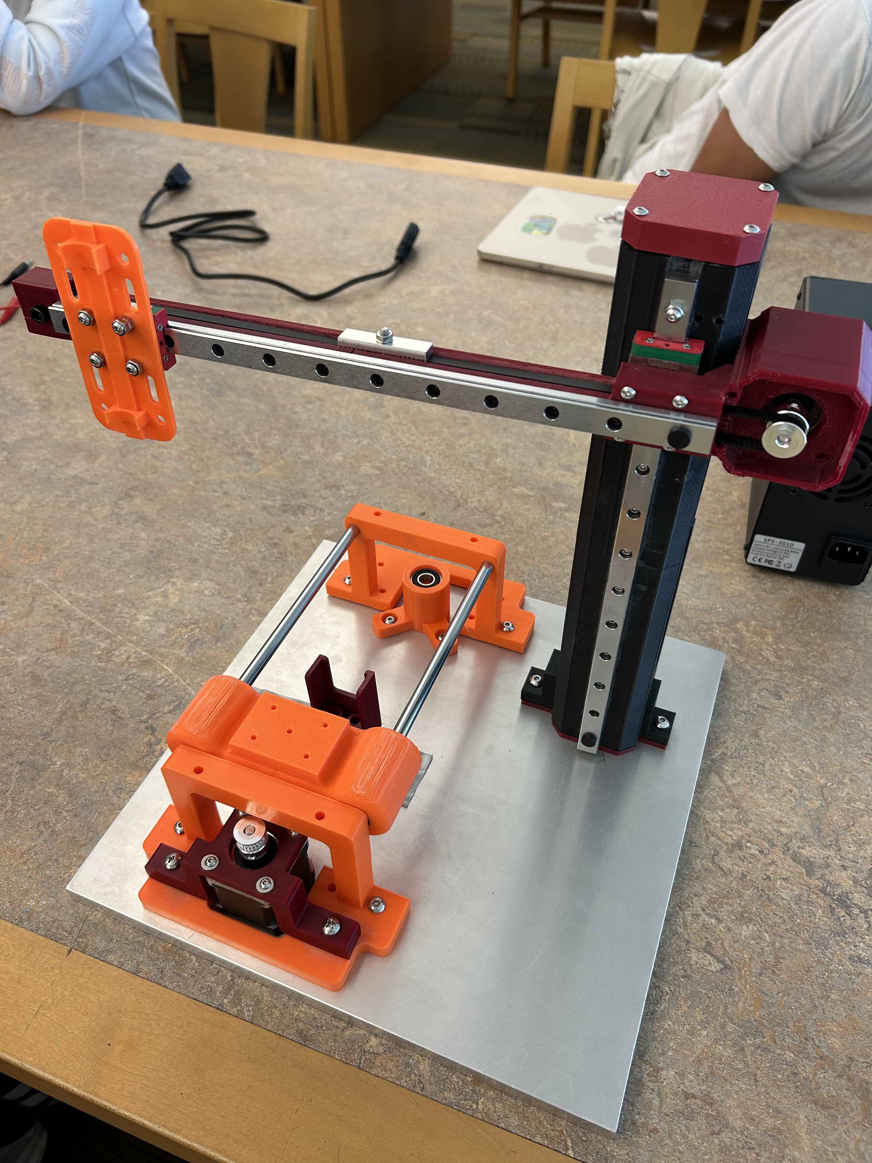
Assembled gantry on the aluminum base 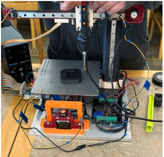
Toolhead over a printed part on the bed 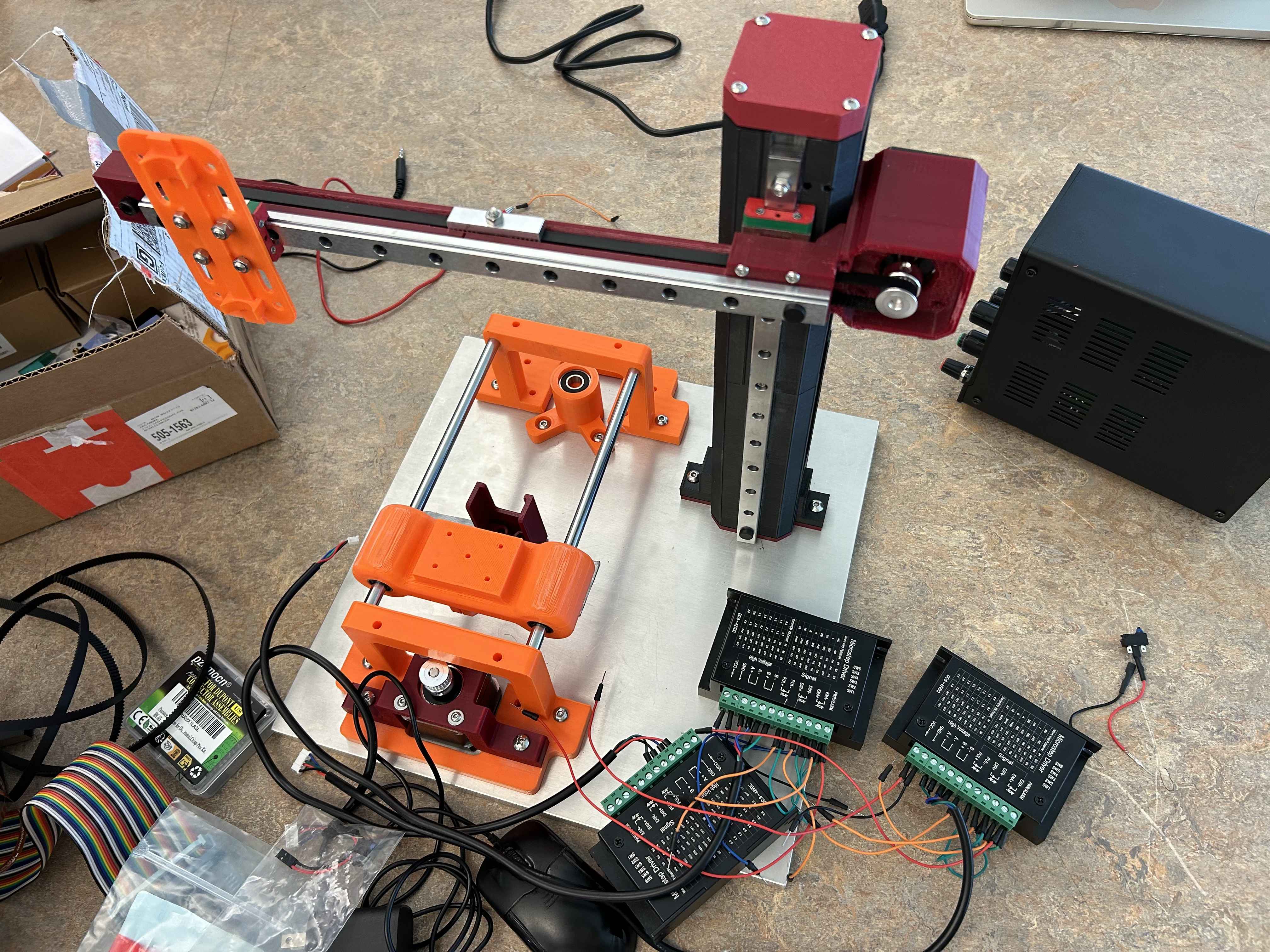
Shop assembly — motion hardware laid out At the bench with the prototype
What I established & built
- Base assembly — rigidity, alignment, and mounting for the full XYZ system
- Y-axis motion on the base — rods, bearings, belt drive, and motor housing
- Stainless bed plate, clamping under the slider, and insert staging geometry
- Solid models, exploded views, and GD&T 2D drawings for fabrication
- Mechanical gantry structure (X/Z), 3D-printed mounts, and physical build/integration (non-electrical)
How it came together
- 01Problem framing — replace manual heat-set insert installation with a low-cost automated cell (~$400 budget class constraint) that improves alignment and insertion depth.
- 02Architecture — three primary mechanical assemblies: base, horizontal/vertical motion gantry, and tool/clamp path; inserts staged on dowel pins beside the workspace.
- 03Base design — 12×12×0.5 in aluminum plate sized for stiffness; drilled and tapped for M5 mounts; PLA support mounts and plate slider printed and bolted on.
- 04Y-axis integration — two steel rods, linear bearings, NEMA 17 belt drive (~16 in GT2 belt, 20-tooth pulley) for smooth, controlled table motion.
- 05Work surface — 8×8×0.125 in stainless bed plate on the slider (headless M3); holes for dowel pins epoxied in place to stage inserts in columns.
- 06Gantry motion — linear-rail X (belt) and lead-screw Z (T8) for toolhead positioning; iterated mounts, spacers, and lead-screw support during build for clearance and alignment.
- 07Documentation — SolidWorks assembly views plus GD&T callouts on the aluminum base and stainless bed for flatness, hole position, and fit.
- 08Bring-up — assembled physical machine, verified structural rigidity and Y-axis motion, and integrated subsystems for testing (camera/electrical stack handled separately).
Tools
- SolidWorks
- GD&T drawings
- PLA additive manufacturing
- Aluminum & stainless machining
- Linear rails / rods / bearings
- NEMA 17 · GT2 belt · T8 lead screw
Outcomes
- Designed and fabricated the 12×12×0.5 in aluminum base as the structural foundation
- Integrated Y-axis belt drive (NEMA 17, 20-tooth pulley, ~16 in belt) with steel rods and linear bearings
- Machined/tapped mounting features; 8×8×0.125 in stainless bed plate with epoxy-set dowel pins for insert staging
- Produced SolidWorks models and GD&T drawings for the base and bed plate
- Built and iterated the mechanical gantry (X belt / Z lead screw), mounts, and shop assembly for repeatable motion
Coming next: Demo videos of motion and insert placement
The Can Arm is a compact 3-DOF manipulator that transfers objects (empty soda cans) through a fully programmed servo sequence — no hand-cranking, no potentiometer babysitting. I designed and fabricated the mechanical stack in SolidWorks: base and cover, arm and arm holder, rotating assembly with ball bearing, servo mounts, and a left/right claw pair closed by an MG995-driven gear mesh. COTS MG995 servos and an Arduino kit handled actuation and control; a variable DC supply fed the motors through a breadboard while the Arduino drove a repeatable open-loop trajectory (home → grasp → lift → rotate → place). The arm mounts to a 3D-printed base on a wooden plank for stiffness — the same shop instincts as my heat-insert gantry and internship drawing reviews: design for printability, document with BOM/schematics, then iterate until the sequence hits every time.
Demo video
Bench bring-up — joint motion and gripper under Arduino control
Manufacturing drawings
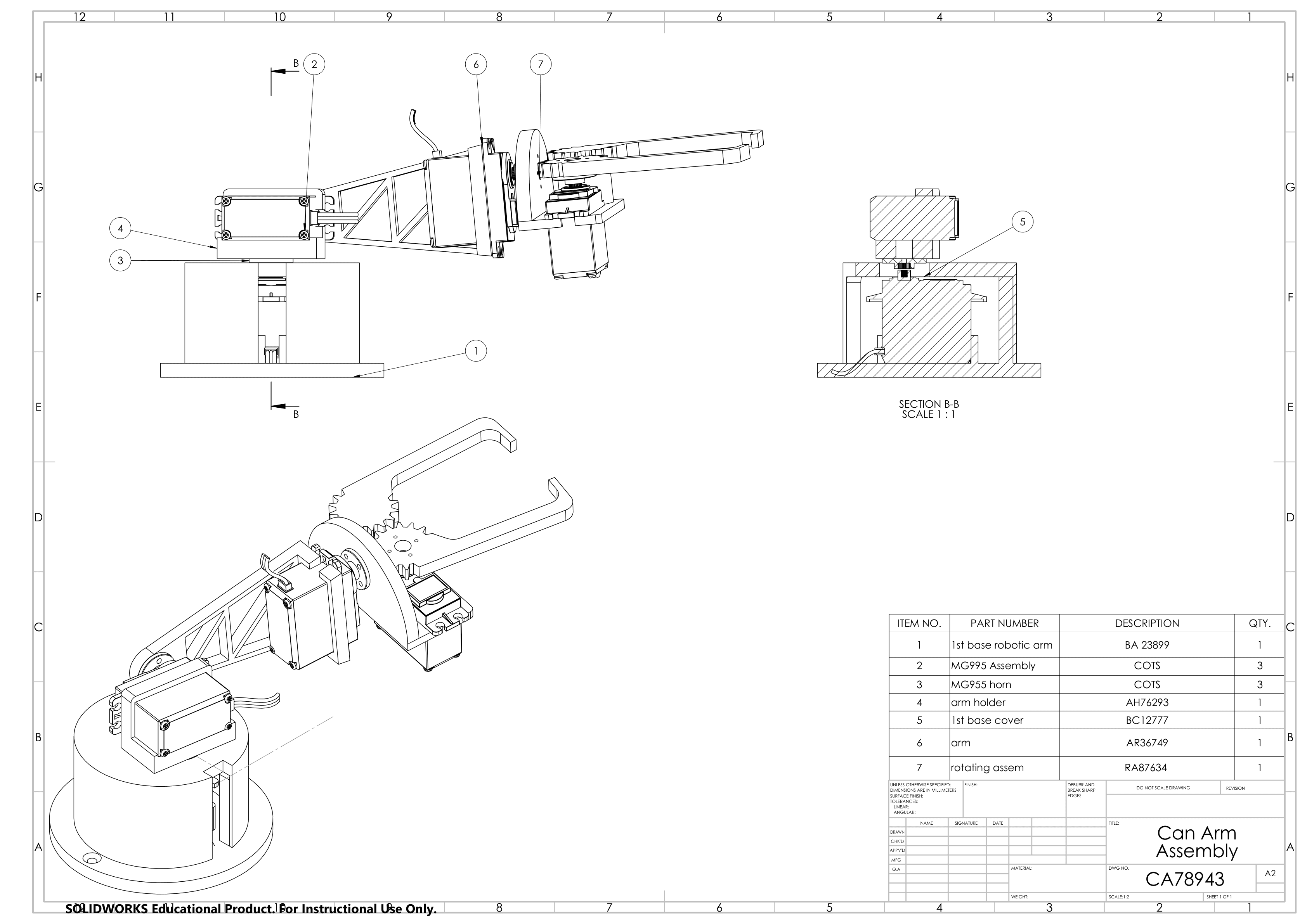
Can Arm Assembly — section B-B + BOM (CA78943) 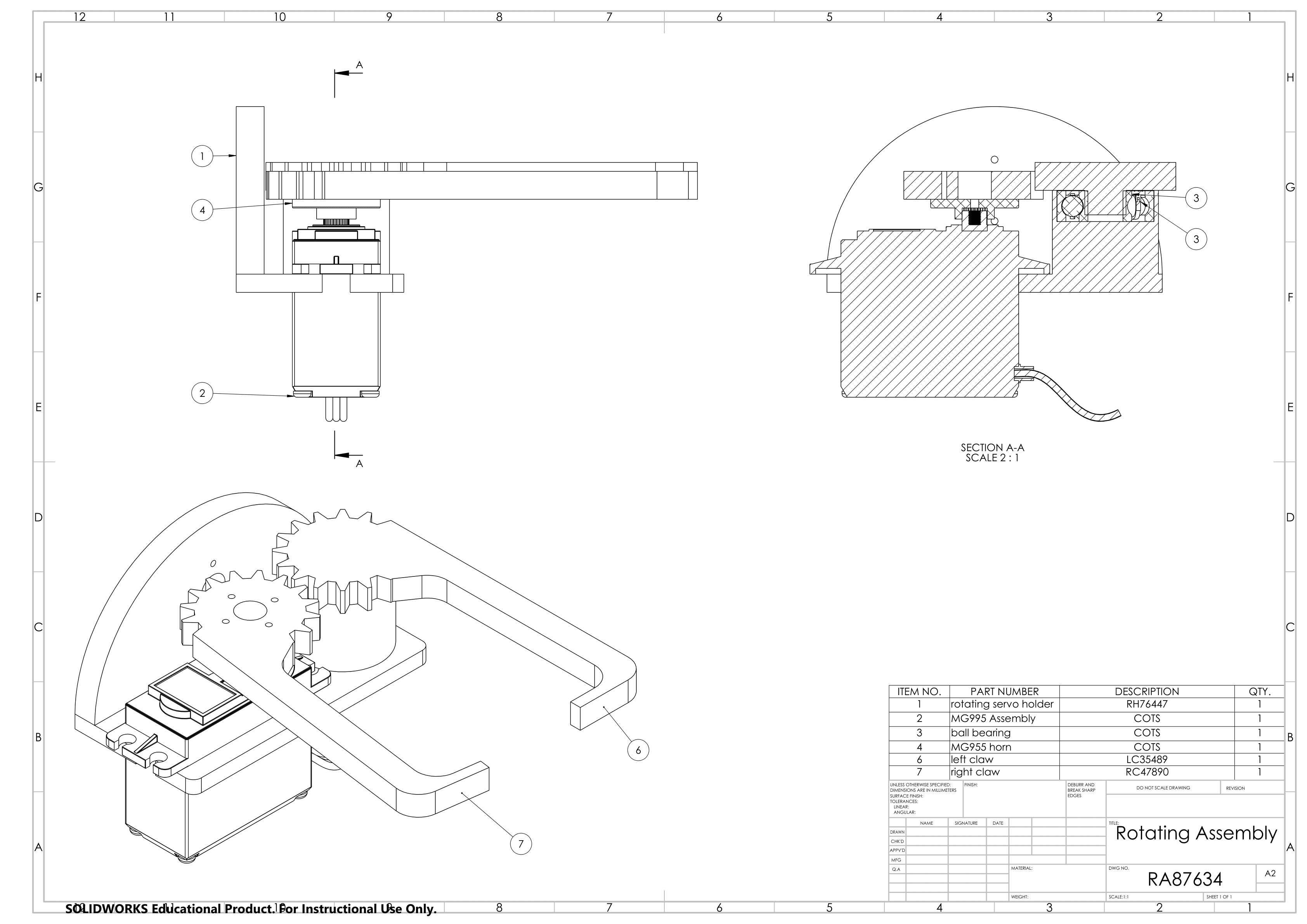
Rotating assembly schematic — claws, bearing, MG995 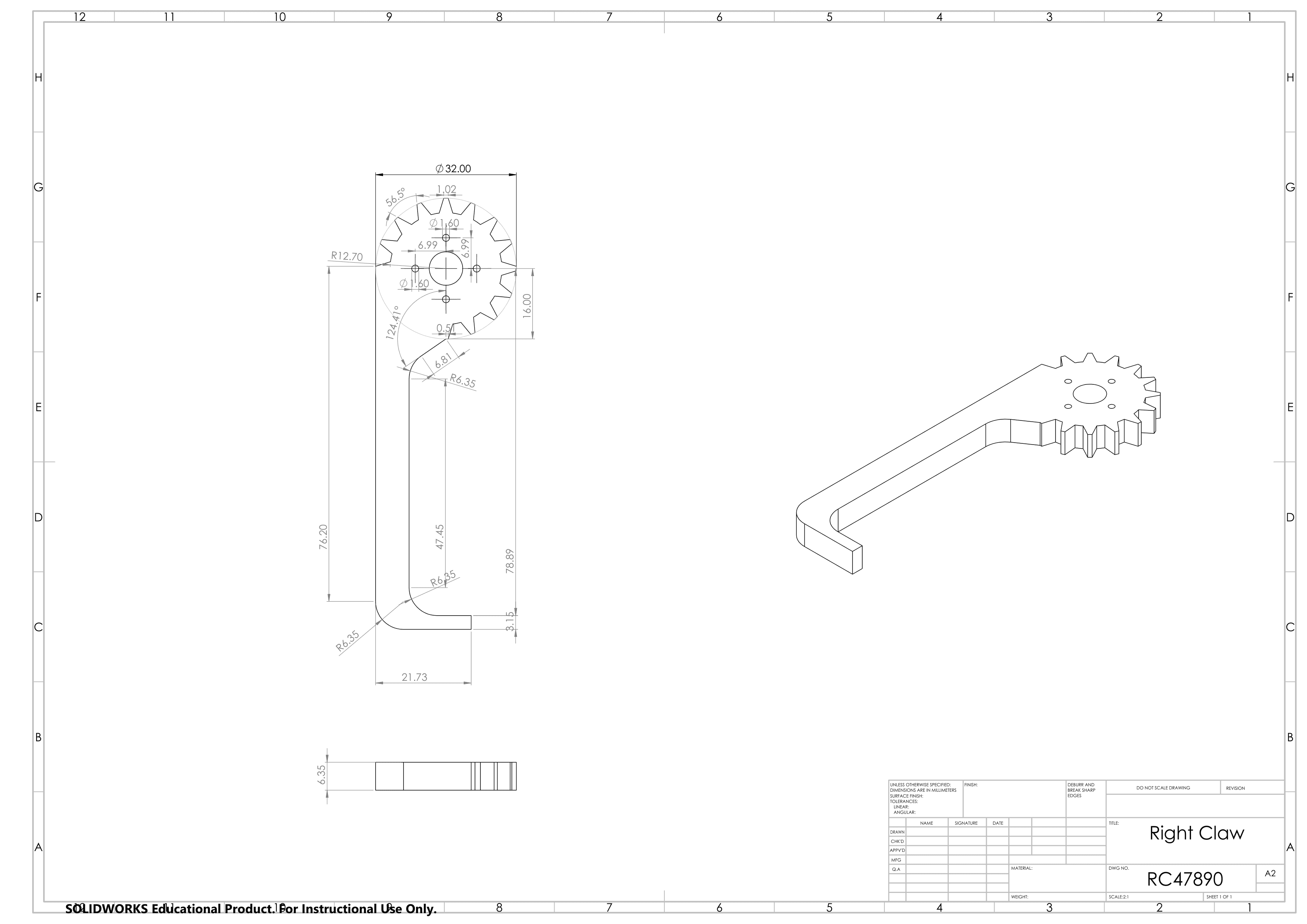
Right claw detail drawing (RC47890) 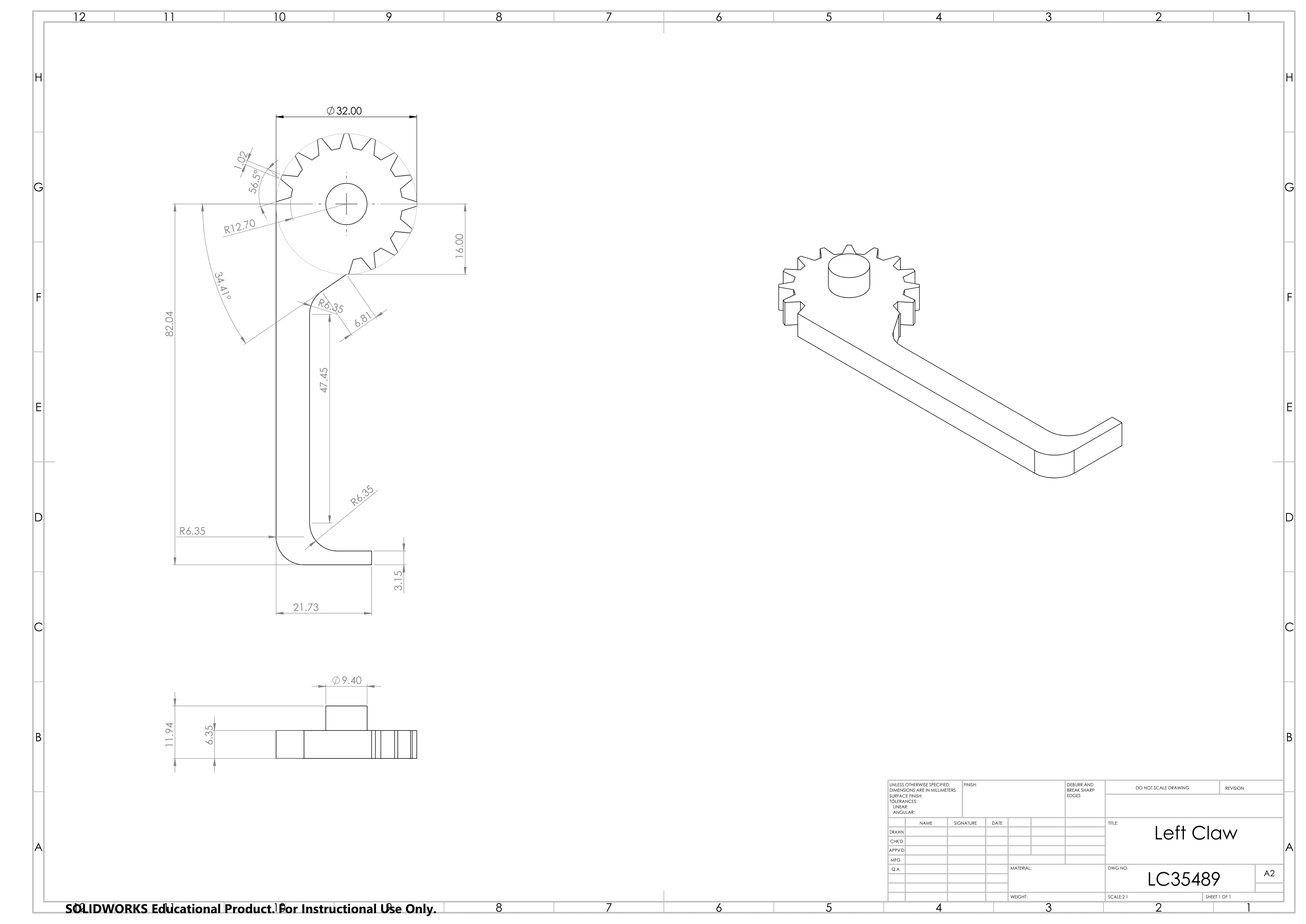
Left claw detail drawing (LC35489) 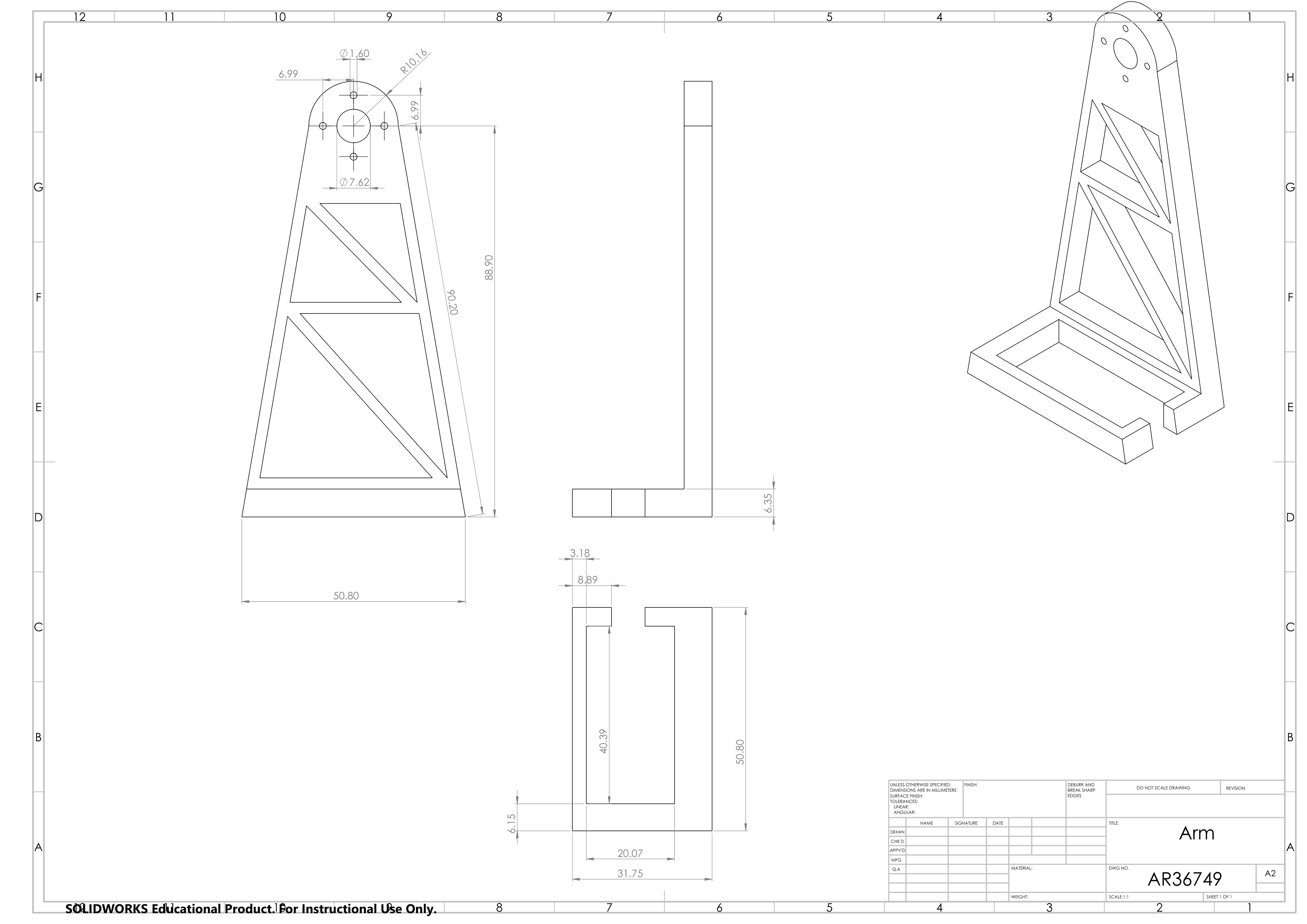
Arm link drawing (AR36749) 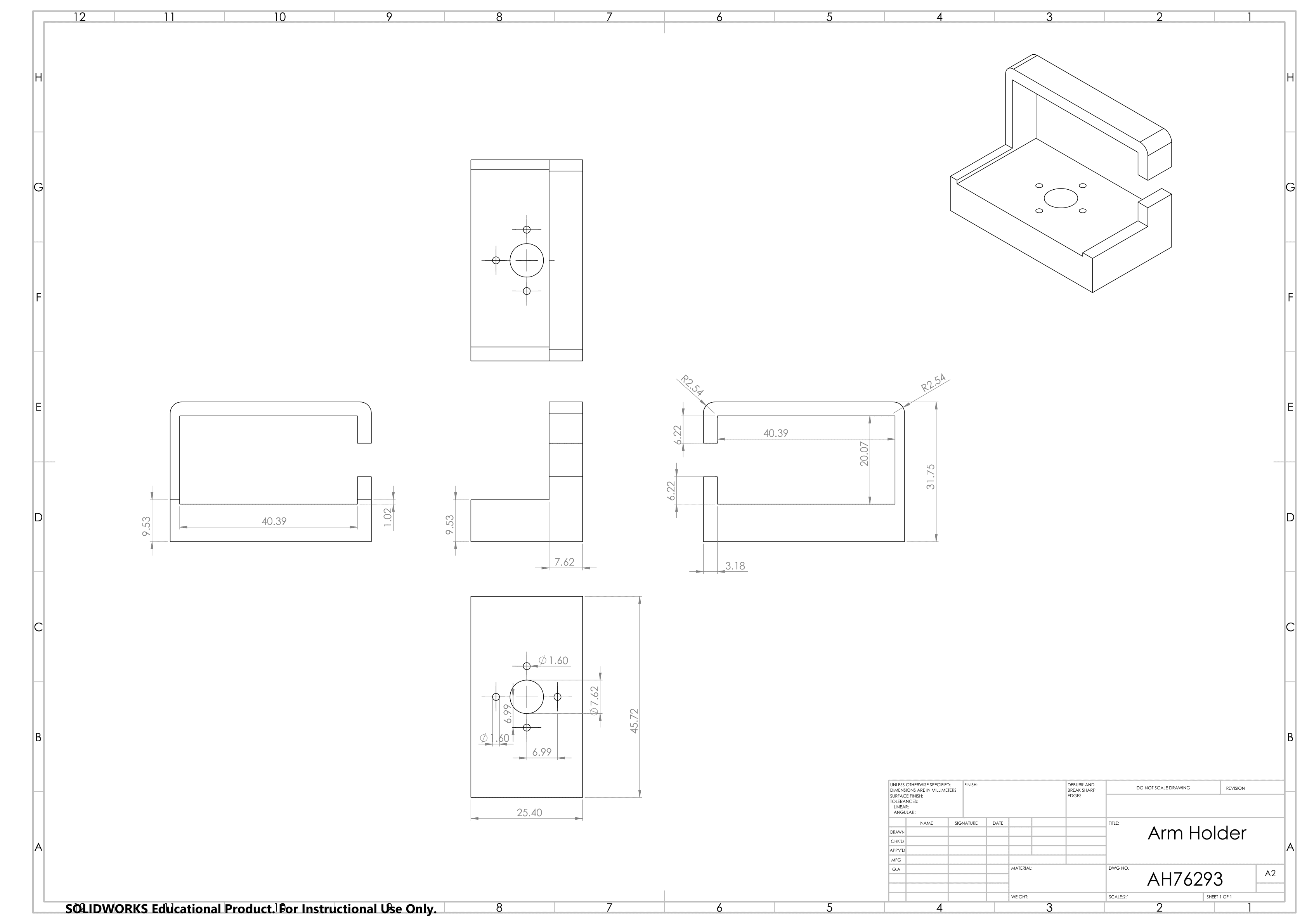
Arm holder drawing (AH76293) 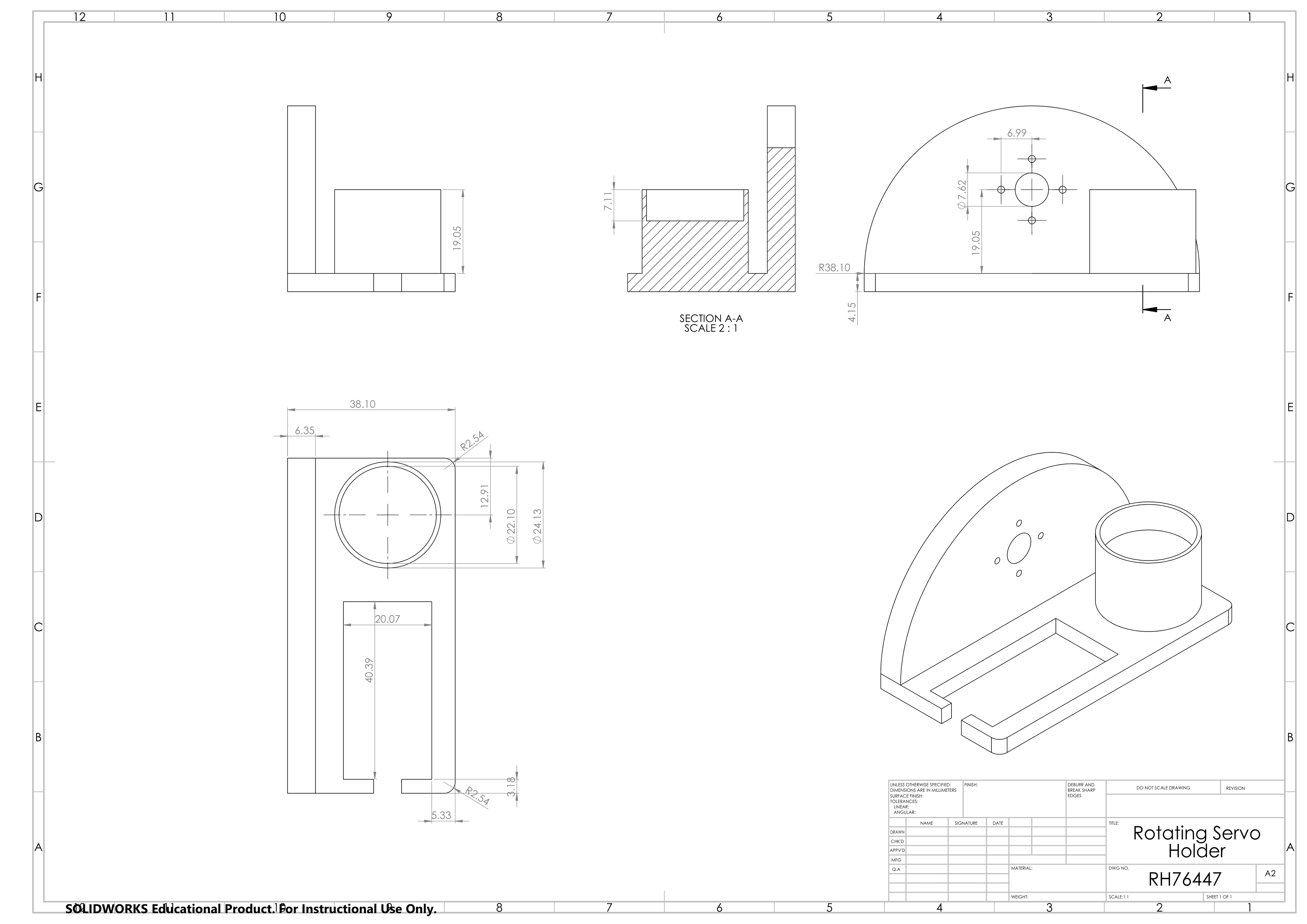
Rotating servo holder (RH76447) 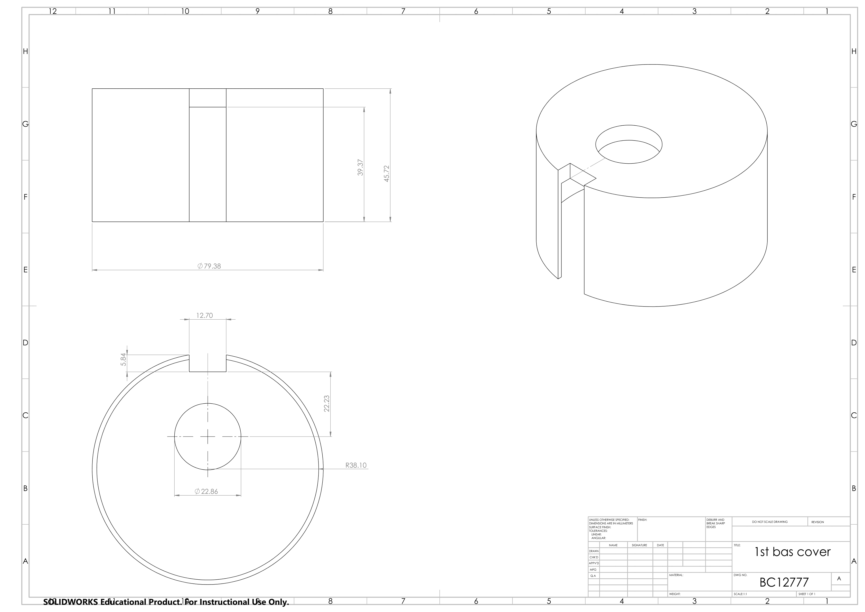
Base cover drawing (BC12777)
Build photos
Geared claw + MG995 — end-effector close-up 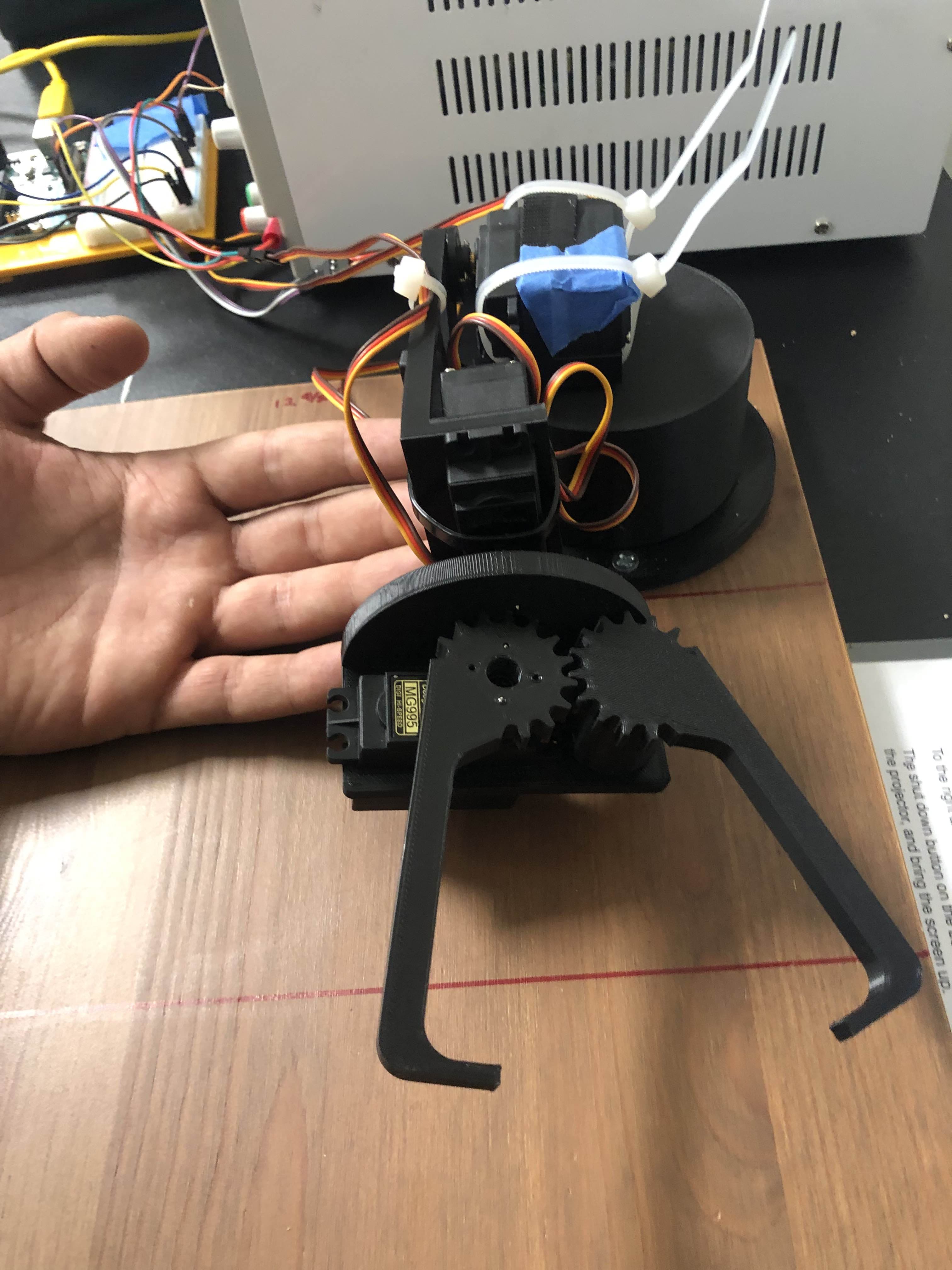
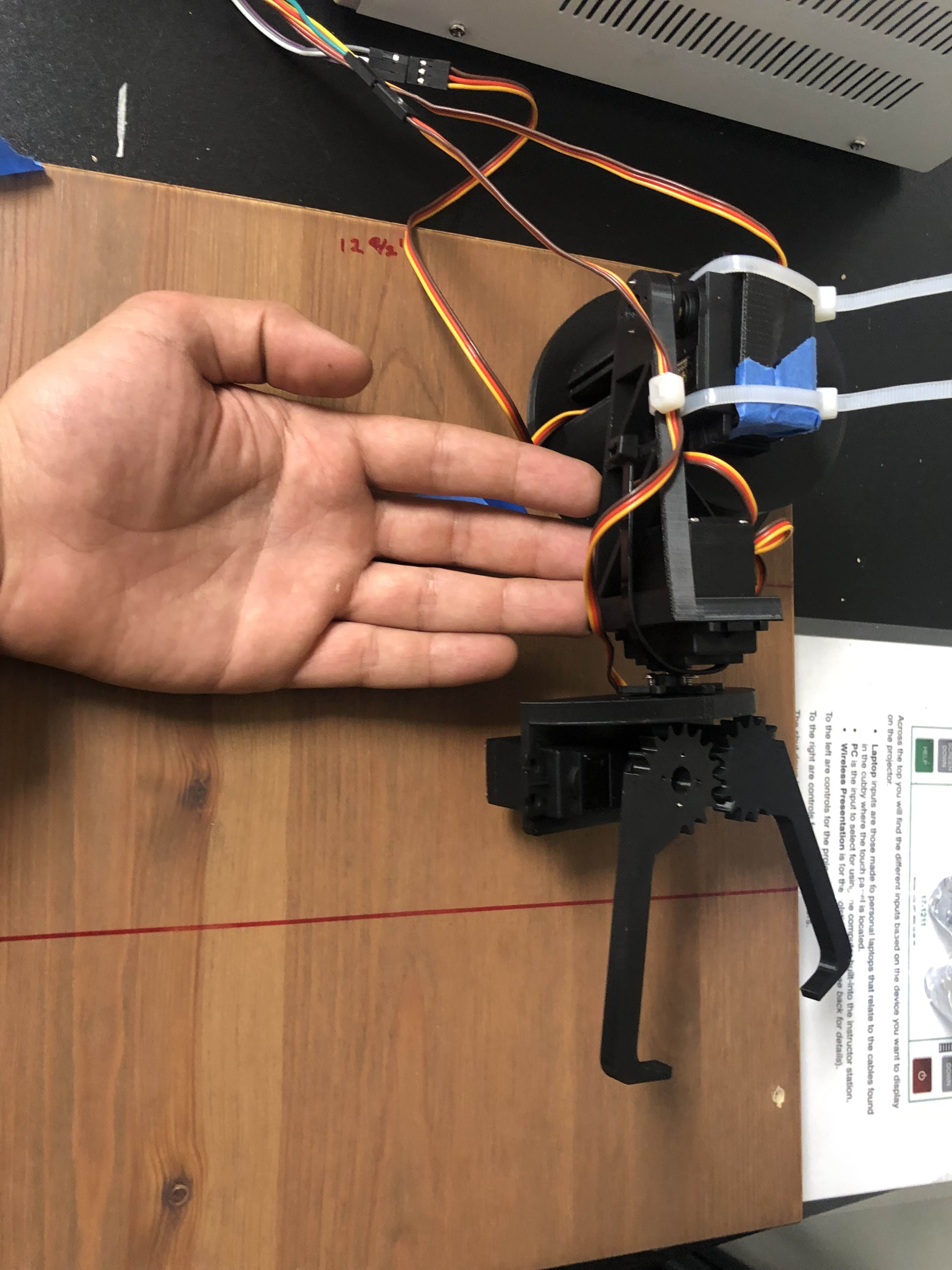
Gripper scale check on the bench 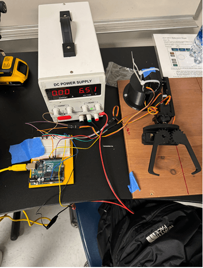
Full setup — arm, Arduino, breadboard, bench supply 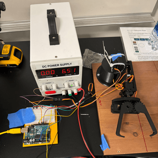
Powered test on wooden base mount
What I established & built
- SolidWorks design of structural and gripper parts (claws, arm, holders, base, covers)
- Assembly drawing with BOM (CA78943) and rotating-assembly schematic (RA87634)
- Detail drawings for right/left claw, arm, arm holder, servo holder, base cover
- Physical build — print, assemble MG995 stack, zip-tie cable management, bench bring-up
- Mechatronics integration — Arduino signal lines, DC supply to servos, scripted transfer path
How it came together
- 01Requirements — automate can transfer with a low-budget team; choose 3 DOF so the mechanism stays simple without sacrificing the task.
- 02Architecture — custom printed structure + COTS MG995s and Arduino; claw gear train for synchronized grasp on cylinders.
- 03CAD — model base (BA 23899), arm (AR36749), arm holder (AH76293), rotating assembly (RA87634), left/right claws (LC35489 / RC47890), covers and servo attachments.
- 04Documentation — Can Arm Assembly sheet with section views + BOM; individual part drawings with mm dimensions and section callouts for print/fab.
- 05Fabrication — FDM-print structural parts; integrate three MG995s with horns; add ball bearing in the rotating assembly for smoother yaw.
- 06Controls — scrap flaky potentiometer teleop; hard-code a servo angle sequence that homes, closes the claw, lifts, rotates the base, and places the can.
- 07Integration — power servos from a bench DC supply (~6.5 V) via breadboard; Arduino handles PWM; mount the base to a wooden plank for demo stability.
- 08Validation — repeat the transfer sequence until placement is consistent; iterate zip-ties, mounts, and claw mesh for reliability.
Tools
- SolidWorks (parts, assembly, drawings)
- FDM 3D printing (PLA)
- MG995 high-torque servos
- Arduino sequencing
- Geared end-effector design
- DC bench supply & breadboard wiring
Outcomes
- Full Can Arm Assembly with BOM — base, arm, rotating assembly, claws, covers
- Part drawings for claws, arm, holders, base, and servo attachments (mm detailing)
- 3-DOF architecture sized to the transfer task (base rotate, shoulder extend, claw close)
- Motor-driven geared gripper reliable on cylindrical cans
- Automated Arduino sequence that homes, manipulates, and places without manual inputs
- Stable wooden-plank mount for weight-bearing during demos
Commercial footwear testers are either crude vertical presses that miss the rolling contact of real walking, or full robotic gait labs that are too expensive for most engineering spaces. I designed a laboratory-scale shoe durability and quality testing machine that sits in an approximate 2 ft × 2 ft footprint while still reproducing the stance-phase sequence that actually wears a sole: heel strike → mid-stance peak → toe-off load transfer. The architecture is deliberately mechanical — a revolving linkage on a ~30 lb rotating flywheel converts motor rotation into repeated foot motion; when kinematics showed the flywheel mass alone could not hit human-scale walking forces (~165–195 lb), I sized a spring-assist pack to ~75 lb/in using Hooke’s law at ~50 rpm. The frame is AISI 1020 steel, checked in SolidWorks Simulation (beam model) under 150 lbf vertical + 22.5 lbf lateral: peak stress ~0.349 ksi, max deflection ~2.1×10⁻⁴ in, first natural frequency ~889 Hz vs. ~41.7 Hz motor drive — stiffness and resonance margin without guessing. A Dorner 2200-class low-profile conveyor carries the shoe under a foot mold instrumented with ~550 lbf compressive load cells at heel, mid-foot, and forefoot (HX711 24-bit ADC) so load progression across the stance phase is measurable, not assumed. Biomechanics drove every trade: literature on gait (Winter, Perry) and robotic footwear testers (Nguyen et al.) pushed the design away from “stamp and crush” and toward continuous directional load transfer on a compact, repeatable platform.
CAD & mechanism views
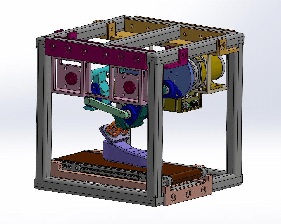
Final CAD assembly — frame, conveyor, linkage, foot mold 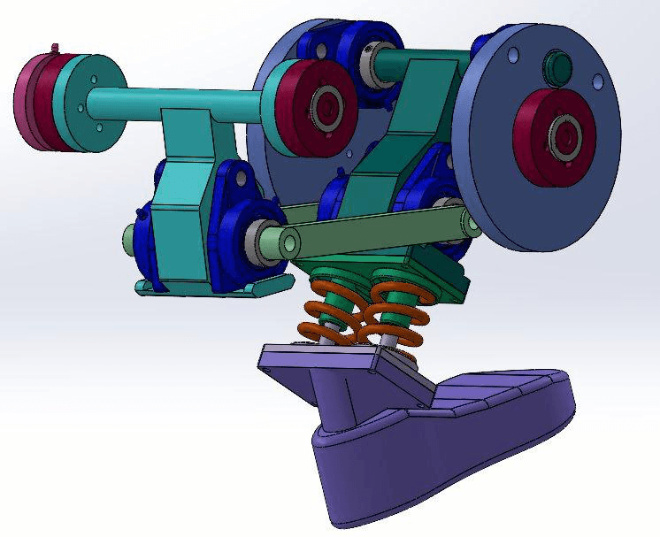
Revolving linkage + flywheel — rotation → gait motion 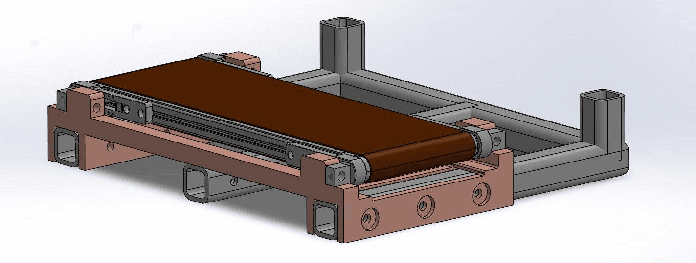
Dorner 2200-class conveyor / treadmill layout 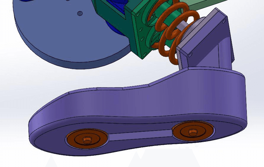
Foot mold — load cells at heel, mid-foot, forefoot
Analysis, FEA & data
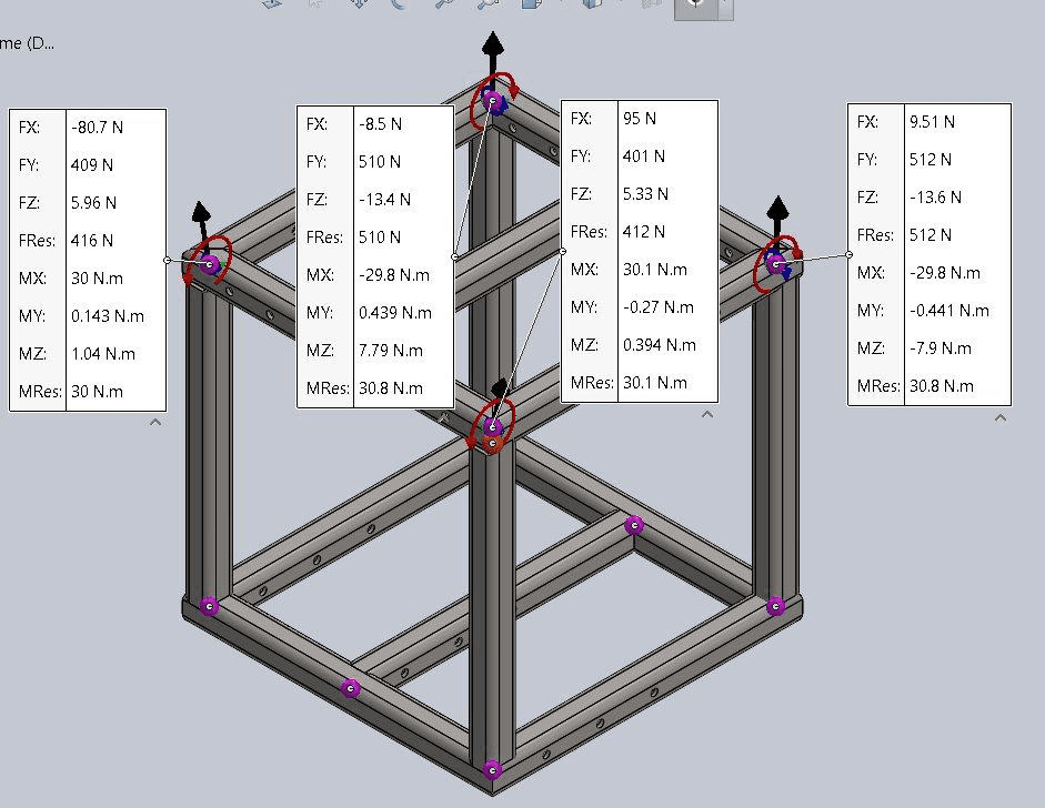
Frame FEA — AISI 1020, ~0.349 ksi / ~2.1e-4 in 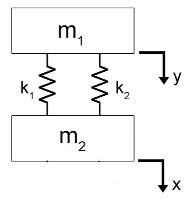
Spring / FBD model — dynamic loading assist 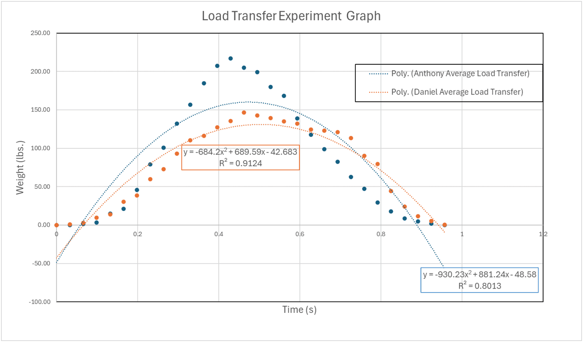
Gait-cycle load curve — heel strike → toe-off 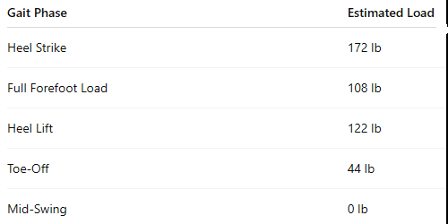
Table — estimated walking load conditions 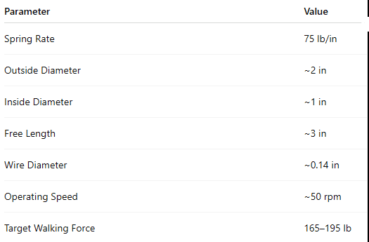
Table — spring design parameters (~75 lb/in) 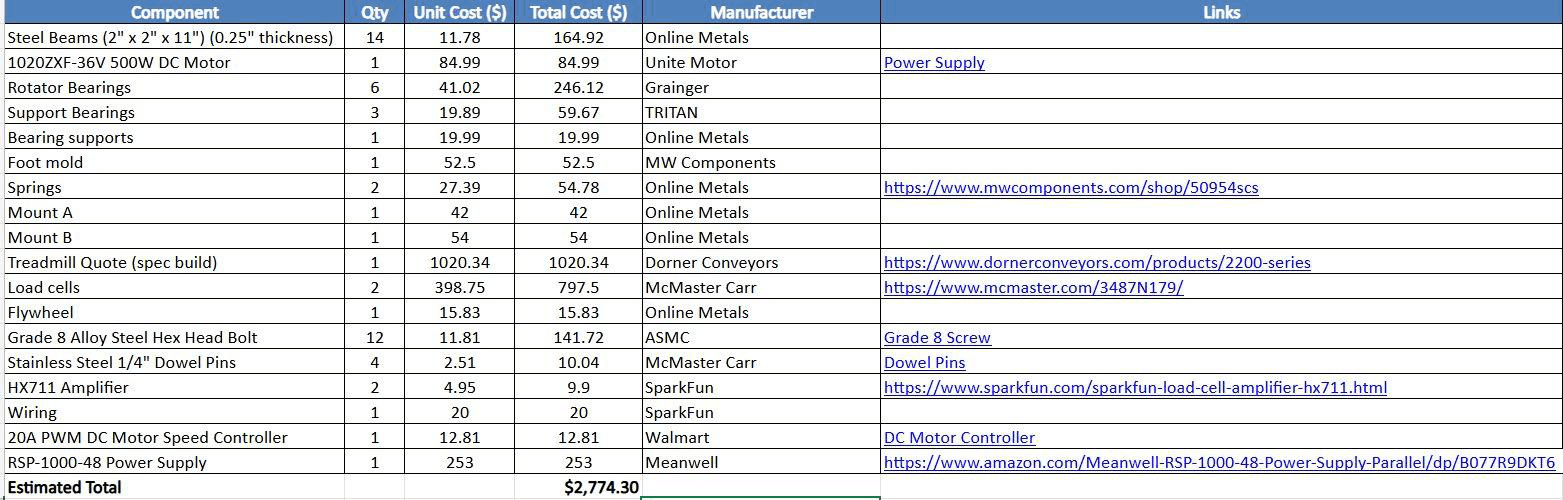
Table — cost / component breakdown
Design scope & analysis ownership
- Problem framing — replace human-subject variability with a repeatable mechanical gait-cycle platform for sole wear and load distribution
- Mechanism architecture — revolving linkage + flywheel (~30 lb rotating assembly) for heel-strike → mid-stance → toe-off motion, not vertical stamping
- Spring-assist sizing — free-body / Hooke’s-law work when flywheel inertia alone under-delivered human walking force
- Structural FEA — AISI 1020 beam-element frame under operating vertical/lateral loads; vibration screen vs. motor frequency
- Conveyor & instrumentation — Dorner 2200-class treadmill path; foot-mold load cells + HX711 for plantar load progression
- Impact / friction calculations and costed BOM-level trade study for motors, bearings, springs, sensors, and structure
How it came together
- 01Biomechanics first — map the stance phase (heel strike, mid-stance peak, toe-off) from gait literature; reject pure compression presses because they miss rolling contact and forefoot load transfer.
- 02Benchmark the field — study commercial presses vs. expensive robotic gait simulators (Nguyen et al.); aim for a simplified but mechanically honest tester that a lab can actually house and afford.
- 03Mechanism choice — revolving linkage on a flywheel so continuous rotation becomes repeated downward/forward foot motion; estimate ~30 lb rotating mass and run Newton’s-law / kinematic checks at ~50 rpm.
- 04Force gap → springs — rotating assembly alone cannot hit ~165–195 lb walking loads; size a spring pack to ~75 lb/in (2 in OD / 1 in ID / 3 in free / 0.14 in wire) so assist force fills the gap without industrial servos.
- 05Frame stiffness — SolidWorks Simulation beam model in AISI 1020; apply 150 lbf vertical + 22.5 lbf lateral; confirm tiny stress/deflection and first natural frequency (~889 Hz) far above motor frequency (~41.7 Hz).
- 06Treadmill path — select Dorner 2200-class low-profile conveyor for a tight 2×2 ft envelope; size contact from gait curve (~1.2× BW heel strike ≈172 lb on 143 lb BW) plus impulse impact (~534 lbf) and friction (~176 lbf at μ=0.33).
- 07Sense the sole — foot mold with compressive load cells (~550 lbf, ±0.276 lb class accuracy) at heel, mid-foot, and forefoot; HX711 24-bit ADC so stance-phase load migration is a measured trend, not a sketch.
- 08Motors & cost — DC drive sized for ~50 rpm under load (torque vs. packaging vs. industrial servo cost); subsystem cost table keeps the architecture cheaper than robotic gait labs while staying mechanically complete.
- 09Design closure — lock CAD assembly (frame + linkage + mold + conveyor), document FEA/spring/gait tables, and leave a clear path for adjustable weight brackets, conveyor tracking calibration, and closed-loop motor control.
Tools
- SolidWorks (assembly + Simulation FEA)
- Gait biomechanics (stance-phase loading)
- Linkage / flywheel kinematics
- Spring design (Hooke’s law · ~75 lb/in)
- Impulse-momentum impact estimates
- Dorner 2200 conveyor selection
- Load cells · HX711 24-bit ADC
- Cost & motor sizing trade studies
Outcomes
- Full CAD assembly of frame, flywheel linkage, foot mold, and conveyor integration in a ~2×2 ft lab footprint
- Spring system sized to ~75 lb/in (≈2 in OD, 1 in ID, 3 in free length, 0.14 in wire) to reach ~165–195 lb walking loads at ~50 rpm
- Frame FEA on AISI 1020 — ~0.349 ksi peak stress, ~2.1×10⁻⁴ in deflection, ~889 Hz first mode vs. ~42 Hz drive
- Heel-strike impact estimate ~534 lbf and friction ~176 lbf (μ≈0.33) to size conveyor contact loads for a 143 lb reference body weight
- Multi-zone load-cell layout (heel / mid-foot / forefoot) with ~550 lbf cells and HX711 readout for stance-phase load transfer
- Subsystem cost breakdown showing a path well below commercial robotic gait simulators
Toolkit
Skills & tools
A cross-section of CAD, analysis, hands-on builds, and collaboration from coursework, internships, and campus teams.
Design & CAD
- SolidWorks (parts, assemblies, drawings)
- GD&T & manufacturing drawings
- BOM & assembly schematics
- AutoCAD / Revit
- Design for 3D printing
Analysis
- SolidWorks Simulation (FEA)
- Linkage / spring / impact sizing
- Thermal & fluid calculations
- Aerodynamics (XFLR5)
- MATLAB
- Excel modeling (VLOOKUP)
- Equipment & data comparison
Make & mechatronics
- Machine design & gantry builds
- Servo / stepper integration
- Arduino sequencing
- Linear motion systems
- Shop fabrication & bring-up
Collaboration
- Project coordination & RFIs
- Technical presentations
- Team leadership
- Field surveys & job walks
- Cross-discipline teamwork
Next step
Get in touch
Open to mechanical engineering internships and full-time roles across design, analysis, manufacturing, aerospace, and related fields.